Pages Menu
Categories Menu

Posted in Top Stories

Data Analytics for the Chiplet Era

This article is based on a paper presented at SEMICON Japan 2022.

By Shinji Hioki, Strategic Business Development Director, Advantest America

Moore’s Law has provided the semiconductor industry’s marching orders for device advancement over the past five decades. Chipmakers were successful in continually finding ways to shrink the transistor, which enabled fitting more circuits into a smaller space while keeping costs down. Today, however, Moore’s Law is slowing as costs increase and traditional MOS transistor scaling have reached its practical limits.

The continued pursuit of deep-submicron feature sizes (5nm and smaller) requires investment in costly extreme-ultraviolet (EUV) lithography systems, which only the largest chip manufacturers can afford. Aside from lithography scaling, approaches for extending Moore’s Law include 3D stacking of transistors; backside power delivery, which moves power and ground to the back of the wafer, eliminating the need to share interconnect spaces between signal and power/ground lines on the wafer frontside; and heterogeneous integration via 2.5D/3D packaging with the fast-growing chiplets. All these new constructs have been formulated to enable the integration of more content into the package.

With these new approaches come heightened package density and stress and much lower defect tolerances. Tiny particles that were once acceptable can now become killer defects, while tighter packing of functionality in these advanced packages creates more thermomechanical stresses. In particular, memory devices cannot tolerate high heat, as the data they hold can be negatively impacted. Large providers of data centers need to prevent silent data corruption – changes in data that can result in dangerous errors, as there is no clear indication of why the data becomes incorrect. Meanwhile, in the automotive space, device volume and density have exploded. Where cars once contained around 50 semiconductors, today the average car packs as many as 1,400 ICs controlling everything from the airbags to the engine.

Quality and reliability assurance test

All of this points to the fact that assuring quality and reliability has become a key challenge for semiconductors. Quality and reliability (Q&R), both essential, are two separate concerns – does the semiconductor work in the long term as well as the short term? Quality assurance, in the short term, has traditionally relied on functional, structured, and parametric tests. The test engineer measured a range of parameters (voltage, current, timing, etc.) to achieve datasheet compliance and a simple pass – the device worked when tested. 

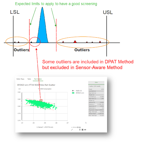
However, the spec compliance test wasn’t enough to assure the reliability of the part – that it would work and continue working over several years’ use in the end product. To assure reliability, semiconductor makers usually apply accelerated electrical, thermal, and mechanical stress tests and inspection, utilizing statistical data analysis on the results to flag outliers that are suspected as potential reliability defects. (See Figure 1.) As the complexity increases, the difficulty of screening unreliable units continues to mount.

Figure 1. Quality and reliability defects are very different in form, nature, and tolerance limitations (LSL = lower specification limits; USL = upper specification limits). Reliability assurance is growing increasingly difficult in the face of heightened package complexity.

The problem with implementing simple statistics to perform reliability testing is that, while obvious outliers will be detected, it’s much more difficult to detect devices that may fail over time and prevent RMAs (Return Material Authorizations), especially in automotive and other mission-critical applications. Once a system fails in the field, engineers are under pressure to analyze the root cause and implement corrective actions. In an example presented at SEMICON West 2022, Galaxy Semiconductor illustrated how tightening test limits to catch more failures takes a significant toll on yield. Very aggressive dynamic part average testing (DPAT) caught just one failure out of 50 RMA units and caused 12.6% of the good units to be lost. Introducing a machine learning (ML)-based model, however, produced far better results. In the same example, utilizing ML-based technologies enabled 44 out of the 50 RMA failures to be detected, with a yield loss of just 2.4%. 

ML + test = enhanced Q&R assurance

Computing power for artificial intelligence (AI) is rising quickly. Well-known R&D firm OpenAI has reported that the computational power for AI model training has doubled every 3.4 months since 2012 when companies like Nvidia began producing highly advanced GPUs, and data-intensive companies like Google came out with their own AI accelerators. These advancements sped AI learning’s computing power. By projecting these advancements into semiconductor test, we know that applying AI and ML technologies to the test function will enable test systems to be smarter so that they learn how to identify more defects – and more types of defects – with more in-depth analysis.

Today’s smaller geometries and increased device complexity require more AI/ML power to enhance data analytics. Data analysis used to be done in the cloud or on an on-premise server. The tester would send data to the cloud or server and wait for the analysis results to judge defects, losing a full second of test time or more – a large deficit in high-volume manufacturing operations. Edge computing, on the other hand, takes only milliseconds, delivering a huge benefit in test time savings.

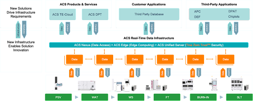
To fully utilize ML technology, we developed a solution to pair our leading-edge testers with ACS Edge™, our high-performance, highly secure edge compute and analytics solution. The ACS real-time data infrastructure enables a full cycle of ML model deployment, real-time defect screening using the ML model, and ongoing retraining of the model to ensure sustained learning. The ML function speeds the detection of outliers, with ACS Edge immediately providing feedback to the tester. Figure 2 illustrates this cycle.

Figure 2. The ML model development retraining cycle feeds data into ACS EdgeTM, which communicates with the V93000 for concurrent test and data analysis.

On-chip sensors for silicon lifecycle management

Another technology in development that many in the industry are excited to see come to fruition is silicon lifecycle management (SLM) to predict and optimize device reliability even more efficiently. Large wafer foundries produce terabytes of data per day – but less than 20% of this large volume of data is useful, which poses a challenge for reliability screening. The SLM concept involves purposefully designing die to produce meaningful high-value data during manufacturing by embedding tiny sensors on the die to measure a variety of local parameters – temperature, voltage, frequency, etc. – with DFT logic to monitor and assess die behavior at every stage. Smart ML models then use the data generated by the on-chip sensors to detect early signs of reliability degradation. If a particular section of a die exhibits a huge temperature spike, for example, it may signal that the unexpected leakage is happening due to some physical reasons (for example, die cracking or bridging) and will fail at some point if not fixed. This technique enables addressing problems much earlier to prevent potentially catastrophic defects.

With SLM-focused sensor monitoring, more thorough reliability testing can occur at every phase, from the wafer and package level to system-level test and field applications. An automotive board outfitted with these on-chip sensors can detect abnormalities faster and transmit this information to the automotive manufacturer for quicker diagnosis and resolution, e.g., notifying the owner to bring the car in for servicing.

Mechanical and thermal stresses are well-known challenges in 2.5D/3D packages, and on-chip sensors can greatly benefit this area. These sensors can help monitor and detect the early signature of degradation in known high-stress areas identified by simulation. As shown in Figure 3, in a package that has an organic substrate (green) topped with a silicon interposer (gray), the coefficient of thermal expansion (CTE) mismatch can create significant stress at the interface between the two materials, leading to warping, which can cause cracking of die-to-die connections (center red dots) and corner bumps (between grey and green). Heat dissipation in the middle of die stacking (3D stacking in pink) is another challenging area. By placing on-chip sensors near these stress points, the package can be monitored more effectively, and potential issues can be addressed before they become catastrophic. 

Figure 3. Devices with on-chip sensors can automatically detect weak areas and stress points within 2.5D/3D packages, sending data to ML models for analysis and reliability screening.

Chiplet ecosystem challenges

The emerging chiplet ecosystem poses significant challenges for timely root cause analysis. With a 2.5D/3D package containing multiple die from different suppliers, it becomes crucial to identify the cause of low yield rates, especially if the yield drops from 80% to 20% after assembly. However, only 23% of vendors are willing to share their data, according to a 2019 Heterogeneous Integration Roadmap (HIR) survey, which delays the identification of the culprit die from a specific wafer lot. Additionally, not all small chips have the memory space to include a unique die ID, which further complicates the traceability of defects. 

 To address these challenges, it is essential to establish data feed-forward and feedback across the ecosystem. When the fab identifies an issue during in-line wafer inspection, it should feed forward the data for more intelligent electrical testing. The data generated during e-test is then fed back to the fab, creating a closed-loop system. By designing chiplets with heterogeneous integration in mind, it is possible to fully utilize fab data and enhance chiplet quality and reliability assurance. Ultimately, better collaboration and information sharing across the supply chain will enable faster root cause analysis and improved chiplet manufacturing. 

Summary

In today’s semiconductor industry, the demand for smaller and more complex device designs has driven the development of 2.5D/3D packages and chiplets. These advancements have brought new challenges to traditional testing methods, requiring advanced technologies such as AI and ML to ensure reliable, high-quality products. 

 New approaches such as silicon lifecycle management (SLM) using on-chip sensors and machine learning for data analytics offer promising solutions for long-term reliability. While SLM is not yet widely implemented, a commitment to collaboration and data sharing across the chiplet supply chain ecosystem is crucial for success. 

 By utilizing AI and machine learning for test data gathering and analysis, significant benefits can be achieved, including enhanced quality and reliability assurance, cost reduction, and accelerated time-to-market for devices. Implementing these technologies must be a key consideration for chiplet design and testing moving forward.

Read More

Posted in Top Stories

New Power-Supply Card Targets High-Voltage PMIC Test

By Toni Dirscherl, Business Lead, Power/Analog/Control, Advantest Europe

The electronics industry is seeing a move toward higher voltages and currents to deliver sufficient supply and charging power in products ranging from handheld cellphones and tablets to workstations. This trend is evidenced in examples such as the many USB power-delivery (PD) profiles with ratings ranging from 10W (5V at 2A for USB PD 3.0 profile 1) up to 100W (5V at 2A, 12V at 5A, and 20V at 5A up to the 100W limit for profile 5). In addition to higher power levels, today’s consumer products are exhibiting an increasing number of voltage domains, and they require power-management integrated circuits (PMICs) to manage the various voltage levels required for battery charging and other functionalities. The PMICs, in turn, present test challenges that ATE systems tailored for mostly digital devices cannot address due to missing high-voltage sources.

Universal VI instrument

To meet these challenges with a cost-efficient test system, Advantest has added a new card to its Extended Power Supply (XPS) Series for the V93000 EXA Scale™ SoC test platform. The new DC Scale XPS128+HV universal voltage-current (VI) instrument combines a high channel count (128 channels per card) with per-channel voltage and current ranges of up to 24V and up to 1A, creating a test solution that efficiently addresses the test requirements for high-voltage devices such as PMICs. The complete card consists of four 32-channel sub-modules with a test-processor-per-pin architecture (Figure 1).

Figure 1. XPS128+HV assembly (left) and 32-channel sub-module (right).

The XPS128+HV provides full channel compatibility with the low-voltage 256-channel XPS256 card successfully introduced to the market in 2020. The XPS128+HV can cover the same applications in the low-voltage domain as an XPS256, but the XPS128+HV seamlessly extends a system configuration to cover additional high-voltage needs, enabling efficient, highly parallel test of power-management devices with enhanced capability for high-voltage applications.

Figure 2 shows the operating IV characteristics of both cards. The region outlined in green represents the XPS256, which operates from -2.5V to +7V at currents up to 1A per channel. All three regions represent the XPS128+HV card. In addition to the green area of the XPS256, the XPS128+HV can operate from -10V to +15V at 250mA (dark blue outline) and from -1V to +24V at 150mA (light-blue outline).

Figure 2. XPS128+HV operating regions.

As shown in Figure 3, the XPS128+HV switches seamlessly between the -2.5V to +7V, -1V to +24V, and -10V to +15V ranges.

Figure 3. XPS128+HV seamlessly switching between ranges.

Signal quality and accuracy

To ensure signal quality and high accuracy, both water-cooled XPS cards include Advantest’s new Xtreme RegulationTM digital control loop, which can flexibly adapt to changing load conditions. Xtreme Regulation also supports programmable voltage and current slew rate and bandwidth settings (Figure 4) to provide an optimum solution for capacitive, resistive, or inductive loads. The programmable slew-rate function avoids excessive currents and noise during voltage ramps, eliminating current spikes during the initial charge of a capacitor and eliminating voltage noise from stray inductance.

Figure 4. Illustration of the XPS128+HV adjustable bandwidth capability on a 24-V channel.

The cards also include arbitrary-waveform-generation (AWG) and digitizer functions with a 2MS/s sample rate and 18-bit resolution for simultaneous voltage and current sampling. The AWG capability enables generation of current ramps on individual or ganged channels to perform threshold searches and other test methodologies.

Voltage and current modes

The core of the XPS256 and XPS128+HV is a digitally regulated VI source that can seamlessly change operating modes from a force-voltage mode to a force- or sink-current mode—often a requirement for testing power-management components such as low-dropout (LDO) or DC/DC regulators. For example, the seamless mode changes enable the cards to execute the fast test sequences necessary to perform DC/DC and LDO regulation tests and IDDQ current measurements while minimizing test times. 

In addition, the XPS128+HV provides seamless mode switching with no limitations related to transitioning between its high-voltage and low-voltage ranges. The card’s sequencer-controlled range-change capability allows extremely fast, deterministic test times without signal spikes that could harm a device under test (DUT).

The XPS card family delivers an extremely high force and measurement accuracy, often required for precise device trimming and for achieving high yields. Voltage accuracy is better than ±150 µV with a 10-µV resolution, while current accuracy is better than ±50 nA with a 100-pA resolution. 

Protective features

The XPS128+HV and XPS256 both offer several protection features. All channels are protected against external exposure of ±80V. The VI source features a patented fast current-clamp capability to protect load-board components, probe-card needles, and DUT sockets in case of a DUT short circuit, limiting inrush currents within less than 2 µs until the programmed clamp value is applied (shown in Figure 5). 

Figure 5. XPS128+HV current-limit response to simulated DUT short circuit.

To further provide probe-needle protection, the XPS cards perform simultaneous current and voltage profiling across the entire test flow to identify critical conditions such as power hot spots that could lead to damage. This background profiling occurs at 2MS/s. In addition, inline Vdrop monitoring measures the contact resistance for each channel to facilitate adaptive needle cleaning and to help schedule preventative maintenance. The profiling and monitoring offer sophisticated oscilloscope-like triggering capabilities (pre-trigger, post-trigger, and center-trigger) and impose zero overhead, uploading only on demand or upon a programmable alarm condition. Profiling can be seamlessly enabled and disabled without test-program modifications.

Multiple-card systems

The XPS series and other EXA Scale cards can be mixed and matched in a single test system. In a typical application, a V93000 test head might include PS5000 cards for digital I/O test and basic analog and mixed-signal test, a Wave Scale Mixed-Signal High-Speed (WSMX HS) card for noise evaluation and transient analysis, a utility card to supply and control load-board components, an XPS256 card to test low-voltage DC/DC converters and regulators, and an XPS128+HV card to test the high-voltage functionality of USB PD circuits and rapid chargers and to provide high-voltage screening. Both XPS cards allow flexible ganging of channels within each card and across cards without any impact on regulation performance. Ganging enables a combination of multiple channels to provide the current levels needed to test DC/DC converters that require multiple-ampere load currents.

Finally, in addition to PMIC testing, the new XPS128+HV can act as a standard power supply for high-performance-computing and automotive test applications. It can also be used for microcontroller (MCU) test, and it can generate high-voltage pulses for MCU flash programming.

Conclusion

Chipmakers increasingly need to perform multisite parallel test of PMICs that feature multiple voltage domains, and they require a power-supply card with a high channel count, combined with flexibility in voltage and current ranges. With its current rating of up to 1A and voltage rating of up to 24V, Advantest’s new DC Scale XPS128+HV instrument will enable chipmakers to configure a cost-efficient, large-pin-count ATE system with many power VI channels that can test high-current as well as high-voltage components while giving them the flexibility to gang multiple channels, meeting high-current needs at all voltage levels. Having already been implemented at several customer sites, the XPS128+HV VI is now available to the global market.

Read More

Posted in Top Stories

Innovative Memory Test Cell Leverages Scalable Parallelism and Compact Footprint for Final Test

By Zain Abadin, Sr. Director, Device Interface and Handling, and Masahito Kondo, Integrated Test Cell Solution Lead, Advantest

Products ranging from datacenter servers to automobiles require more and faster memory ICs, which must be thoroughly yet cost-effectively tested. As these chips evolve to provide ever higher levels of performance and quality, they are placing increasing demands on the test floor. An effective test solution must meet final-test requirements presented by the increasing bit densities, the power consumption, and the faster interface speeds of evolving memory devices. The solution will include automated test equipment (ATE) as well as a test handler that conveys devices under test to the ATE, establishes the proper test temperature, and sorts tested devices into bins according to their pass/fail status.

An effective approach to memory test requires a shift away from the memory-test paradigm that has dominated test floors for the past two decades. ATE and test handler companies have regularly increased parallelism, but each doubling in device capacity has been accompanied by a double-digit increase in test-system size. A way forward beyond 512 devices under test (DUTs) in parallel requires thinking beyond the handler or ATE individually to consider the configuration and performance of the entire test cell. Key points to address include the impact of system downtime; the effect of a big, heavy test cell and its footprint; and the test complexity that results from device variation and requirements for testing at multiple temperatures.

A successful memory-test-cell concept will maximize productivity while controlling cost of test through several features:

  • Scalability would enable customers to configure their test cells based on current test requirements while retaining the ability to scale up when necessary.
  • A single test cell would support efficient device evaluation at the R&D stage while offering the flexibility to be repurposed for production.
  • At any level of scalability, the test cell would efficiently utilize floor space and optimize overall operating efficiency.
  • Innovative software would apply artificial intelligence (AI) processing and analysis for tracking handler health and scheduling preventive maintenance. 
  • For installations with more than one test cell, independent asynchronous test-cell operation would allow partial production test to continue even during maintenance on one cell.

Fully integrated test cell’s compact design saves floor space 

Advantest is now offering these features in a new minimal-footprint memory-test-cell family called inteXcell. The inteXcell infrastructure currently integrates T5835 memory tester modules, which incorporate full testing functionality for any memory ICs with operating speeds to 5.4Gbps, including next-generation memories ranging from NAND flash devices to DDR-DRAM and LPDDR-DRAM in BGA, CSP, QFP, and other packages. Throughput can reach 36,500 DUTs per hour.

TC5835 features include an enhanced programmable power supply to assist with testing advanced mobile memories, a real-time DQS vs. DQ (strobe vs. data) function to improve yield, a timing training function that is indispensable for high-speed memory tests, and test time reduction and defect-analysis functions based on various device data patterns. In addition to working with the TC5835, the inteXcell platform is designed to work with future memory-test solutions as well.

The inteXcell tester section consists of three units (Figure 1). The first, the AC rack, operates on 220VAC and delivers power to the test cell. Second, the server rack implements the system-controller, test-processor, and handler-controller functions. Third, as many as four test heads can test up to 1,536 devices in parallel. These three units have been designed to fit together into compact test configurations, eliminating the wasted space that can result when trying to integrate separately developed test-cell units. Consequently, inteXcell occupies one-third the floor space a conventional test cell would require.

Figure 1. The inteXcell tester section comprises an AC rack, a server rack, and up to four test heads.

From engineering to mass production

With inteXcell, ICs can be tested on the same platform from R&D through mass production. Figure 2 shows the scalable parallelism that inteXcell deployments can achieve. At the right, a base inteXcell can test 384 devices in parallel for initial engineering work. That cell can subsequently be repurposed for production. As production volumes increase, inteXcell’s scalable parallelism enables the addition of another test cell, providing a total test capacity of 768 devices in parallel. Moving from right to left in Figure 2, the addition of a third inteXcell brings capacity to 1,152 devices in parallel, while adding a fourth brings total capacity to 1,536 devices in parallel.

Figure 2. The inteXcell’s scalable parallelism provides flexibility for customers.

Reducing downtime

The inteXcell handler unit incorporates a new, compact chamber structure to provide an efficient and highly accurate thermal-test environment over an operating temperature range of -40°C to 125°C or, optionally, from -55 to 150°C.  New functions such as an automatic position correction capability and a one-touch type replacement kit also improve maintainability and reduce downtime.

In addition, new HM360 status-monitoring software comprehensively manages maintenance and temperature data for the handler unit, making it possible to develop predictive maintenance notifications using AI analysis. Sensors might detect, for example, that a handler pick-and-place mechanism is not achieving optimum vacuum levels. By monitoring deterioration in the vacuum performance, an AI algorithm could determine the optimum time to schedule maintenance. As illustrated on the far left of Figure 2, in a four-cell installation, production can continue at 75% capacity when one cell is taken offline for maintenance.

Minimizing need for operator intervention 

The production efficiency of the test process is further improved by the optimization of the test cell’s automated guided vehicle (AGV) or overhead hoist transport (OHT) function, which minimizes operator intervention. As shown in Figure 3a, a traditional flow involves obtaining untested devices from the virgin-device lot stock area and conveying them to a high-temperature test stage. The output of this stage will be either a failed device or one that requires further test. In the latter case, the device is conveyed to the cold test stage. The output will be either a failed device or a good device that has passed both hot and cold tests. As Figure 3a illustrates, this process involves eight operator access points requiring a complex scheduler/dispatcher.

(a)

(b)


Figure 3. Whereas a traditional test cell requires eight operator accesses for a two-temperature test, inteXcell reduces that number to four and eliminates the need for one lot stock area.

In contrast, inteXcell simplifies the test flow by completing both hot and cold tests with one lot input, as shown in Figure 3b. This approach eliminates the need to establish and access a lot stock area for parts that have passed the hot test, cutting the number of operator access points to four.

Conclusion

Advantest’s inteXcell platform is the first fully integrated and unified test solution to combine broad test coverage with high-throughput handling in a highly flexible system architecture. The new test cells have a compact structure that enables up to 384 simultaneous measurements per cell while using only one-third of the floor space occupied by conventional test systems. inteXcell’s scalable parallelism enables customers to choose the test capacity they need. In addition, each cell employs an independent asynchronous testing capability and AI-based performance tracking, enabling inteXcell to be configured from one to four testers, resulting in high equipment utilization, and streamlined cell-based maintenance. A four-test-cell implementation can test up to 1,536 devices in parallel with high speed and high accuracy. The inteXcell platform is expected to begin shipping to customers in the second quarter of 2023.

Read More

Posted in Featured Products

Advantest Adds System-Level Testing Capability for Advanced Memory ICs

Advantest installed its first enhanced T5851-STM16G tester capable of nonvolatile memory express (NVMe) system-level test coverage at a major manufacturer of IC memory devices. By expanding the capabilities of its established T5851 platform, Advantest addresses the growing market for testing NVMe solid-state drives (SSDs) using ball-grid arrays (BGAs) in automotive applications.

Over the next five years, the automotive market is expected to become the largest consumer of semiconductor devices. This growth is escalating demand for NVMe BGA SSD devices, which are crucial in advanced driver-assistance systems (ADAS). To develop and economically mass produce these key NAND Flash SSD devices, memory manufacturers worldwide need a highly reliable, cost-efficient test solution.

Designed to perform system-level testing of NVMe BGA SSDs, the T5851-STM16G tester is ideally suited for evaluating any generation of BGA SSDs in either an engineering environment or a high-volume production site. The highly versatile platform can handle devices with multiple protocols, including NVMe, UFS and PCIe, at speeds up to 16 Gbps. The system’s modular, tester-per-DUT architecture supports test flows required for system-level testing of up to 768 devices simultaneously. 

Advantest is taking orders for the T5851-STM16G tester. It is available either as a new tester from Advantest’s factory or as a cost-effective enhancement to users’ existing T5851 or even T583X units.

Read More

Posted in Featured

More than Moore or More Moore?

What’s Next in the Future of High-Performance Computing? In this episode, experts will discuss the plans for the coming era of computing and will reveal how the semiconductor industry is continuously evolving to address the looming high performance compute challenges — moving us beyond Moore’s Law. Listen in as John Shalf, Department Head for Computer Science at Lawrence Berkeley National Laboratory, and former deputy director of Hardware Technology for the Department of Energy Exascale Computing Project, helps us uncover how the semiconductor industry will revolutionize HPC over the next decade.  

https://advantesttalkssemi.buzzsprout.com/1607350/11331203-more-than-moore-or-more-moore-here-is-what-s-next

Read More